
Robotino® communication
Main functionalities
The main functionality of the module is to communicate with the Robotino® . The Robotino® is a mobile robot platform for research and education developed by Robotics Equipment Corporation GmbH and distributed by Festo Didactic.
In case this module is in operation, i.e., the robot control software for the use case demonstration is operated by the end-user, then the end-user cannot perform any modification on this module since this module is part of the robot control software. In case this module is included in another robot control software (developed by third-party SME), then a software developer can implement algorithms for communication with the Robotino® using this module.
The typical application scenario for this module is to implement communication algorithms with Robotino®.
The demonstration is available both for internal and for external use.
Technical specifications
This module is an adaptation of the qDSA protocol of the API1 for Robotino® v2, made in native VIs for use with LabVIEW™ software without the need to call external code.
Hardware requirements of the module: Festo Robotino® v2 (Firmware 670, OS Date: 11.02.2011), Wi-Fi access point (AP) (factory standard accessory), UVC standard Webcam (factory standard accessory).
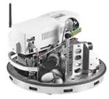
Figure Robotino® v2 mobile robot for education and research
The module consists of two continuously running parallel loops (tasks). One task is dedicated to the keep-alive type communication of the Robotino®, where the Robotino® continuously sends data to the host computer and expects data in response. The other task is the receiver of the camera images, continuously sent by the Robotino® if the camera is enabled.
The module is already available in source code and as a part of a standalone desktop application by contacting the authors of this description.
Inputs and outputs
Inputs:
State of 8 digital outputs
State of 2 relay outputs
Motor speed set-points in RPM for each motor
Reset Position for each motor
Break for each motor
On-board PID controller parameters for each motor
Odometry (Position of the robot)
Set Odometry switch
Camera enable switch
Shutdown switch
IP address of the Robotino®
Constructional parameters of the Robotino®
Outputs:
State of 8 digital inputs
State of the collision detection switch
State of the power button
Sequence number of the communication
Readings of 8 analog voltage inputs
Current readings of each motor
Actual position of each motor
Actual speed of each motor
Actual Odometry (Position of the robot)
Readings of 9 IR distance sensors
Reading of the battery voltage
Is the Robotino® connected switch
Kinematics and inverse kinematics matrices of the Robotino®
Formats and standards
The qDSA protocol of the API1 for Robotino® v2 is used in this module
Training material
undefined
Owner (organization)
Budapest University of Technology and Economics
Documents
Trainings
To learn more about the solution, click on the link below to access the training on the Moodle platform
Robotino® communication