Projection-based Interaction Interface for HRC
Main functionalities

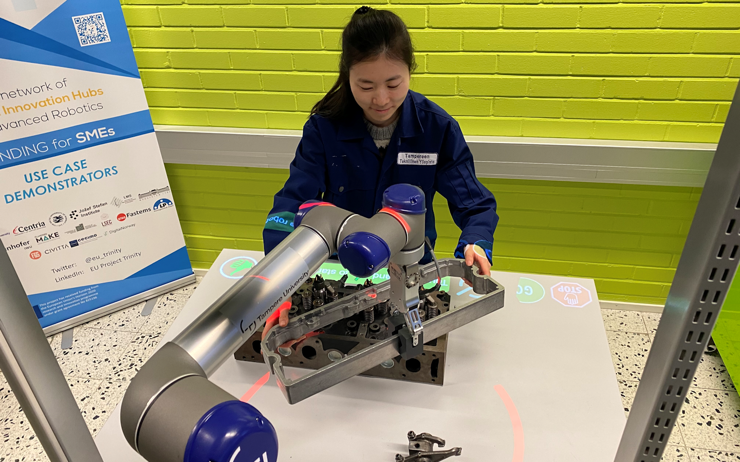
Interface Generation: The module projects interface that the user can interact with by placing a hand over it. The interface includes GO and STOP buttons to control the robot, CONFIRM button and CONFIRM OBJECT button to update workspace model manually. To prevent accidental start of the robot, the START button should be pressed simultaneously with the CONFIRM button.
Technical specifications
The system consists of:
– standard FullHD 3LCD projector.
– Microsoft Kinect v2
– Universal Robot UR5
– Workstation with Ubuntu operating system
The workspace is monitored by the Kinect v2 sensor which can be installed at the ceiling overseeing the whole working area. The frame rate of the sensor is 30 Hz. A standard 3LCD projector is used to project the safety hull and the user interface components on the workspace. The projector outputs a 1920×1080 color projection image with 50 Hz frame rate. Due to the short distance from the ceiling to the workspace the physical projection size can be increased by installing a mirror in 45˚ angle to re-project the image to the workspace. The robot is UR5 from the Universal Robot family.
A modified version of ur_modern_driver and univeral_robot ROS packages are used to establish a communication channel between the robot low-level controller and the projector node. Iai-kinect2 ROS package is used to receive data from the Kinect-2 sensor and further transmit it to the projector node. The sensor monitors the usage of the interface components. The projector node is responsible for creating RGB images of the current status of the workspace for the projector and sending start and stop commands for the robot controller.
Projector, robot and depth sensor are all connected to a single laptop computer that runs the ROS Melodic distribution on Ubuntu 18.04 and performs all computing. Right now, only Kinect v2 and Universal Robot 5 are supported.

Module software nodes and the hardware components
Before the module can be used,
1) projector, robot and sensor must be extrinsically calibrated,
2) placement of the user interface components and size of the virtual safety hull has to be defined,
3) the locations of the interface buttons on the workspace must be defined and
4) wired communication link between PC and robot must be established.
Inputs and outputs
All the data is transferred via a standard ROS transport system with publish-subscribe semantics.The projector node subscribes to topics /joint_states and /trinity/system_data where the robot joint values and the task related data are published respectively. The joint values are used to calculate the shape and position of the safety hull. The text in the information bars and the appearance of other interface components are based on the system data.

In addition, the projector node subscribes to /trinity/sensor/points topic where the depth measurements from the sensor are published. The measurements are used to calculate the usage of the interface components (e.g. is a human hand on the stop button)

Data transport layer
An 1920×1080 RBG image is sent to the project and start/stop command can be published to the robot controller over /ur_driver/dashbord_command topic.

Data transport layer
Formats and standards
ROS communication layer, ROS-industrial, OpenCV, PCL and C++ and Python standard libraries.
– Availability: Module library https://github.com/Herrandy/HRC-TUNI.git
– Application scenarios: Industrial assembly.
– Available for internal/external use.
Owner (organization)
Tampere University, Finland
https://research.tuni.fi/productionsystems/
Trainings
To learn more about the solution, click on the link below to access the training on the Moodle platform
Projection-based interaction interface for HRC
