
Additive TiG welding
Main functionalities
The module uses a KUKA robot to perform metal additive manufacturing of thin wall structures using TIG welding. It uses the simulation program Visual Components as a programming interface and allows for advanced programming functions/commands to be executed on the KUKA robot and rotary table.
The program works by first creating a robot movement in Visual Components. From the movement, multiple layers are automatically generated with a specific height increment and number of layers. This creates a program that can be executed on the KUKA controller to weld thin-wall structures. The movement can be created with either a liner, point to point or path movement.
Benefits of the system:
Flexible system for 3D printing of metal parts
TIG welding has fewer metal properties requirements comparing to MIG welding. (TIG welding supports two different metals welding)
Can create thin-wall structures welding
Being able to repair parts (ex: broken gear wheel) (coming very soon video demonstration).
Significant cost-saving due to, i.e., reduced material used, reduced production time and reduced number of parts in assembly.
Technical specifications
The system consists of an industrial KUKA Robot and a rotary table coupled to the same KUKA controller (KR C2). A Fronius MagicWave 5000, a completely digitized TIG welder, is connected to a PLC and then to the KUKA controller as shown in Fig 1. With the KUKA controller It is possible to set welding parameters and control the welding machines. For this reason, the system is setup with an external computer connected to the KUKA controller, which can control the KUKA robot, rotary table and welding equipment in real time.
To be able to generate the path, Visual Components premium is required.
Visual Components is used to generate a path for the first layer. A python script replicates the first layer with a specific height increment and number of layers.
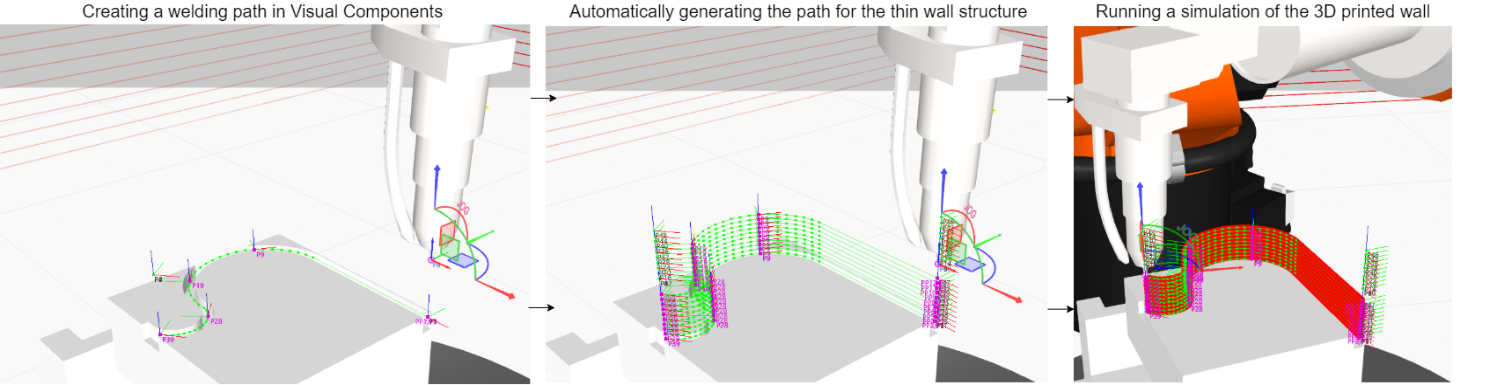
How the 3D structure is generated in Visual Components
Inputs and outputs
Input: Input the welding plate and program the robot and rotary table movement in Visual Components.
Output: A 3D printed thin wall structure
Formats and standards
Visual Components Premium 4.2 (simulation/programming tool), OPC UA standards (Connecting robot and simulation software), translator from Visual Components to the robot and rotary table (made in Python) and KUKA controller with the Robot Sensor Interface (RSI) add-on for real time control of the robot and rotary table.
Owner (organization)
The Owner of the demonstrator is: The Artic University of Norway (UiT) https://en.uit.no/startsida
The Arctic University of Norway is a medium-sized research university that contributes to knowledge-based development at the regional, national and international level. UiT is the third largest university in Norway and northernmost university in the world. UiTs study portfolio covers all classical subject areas from Health Sciences, Social Sciences, Education and Humanities, Science and Technology to Economics, Law, Social Work, Tourism, Sports and Fine Arts. While the key research areas cover the polar environment, climate research, indigenous people, peace and conflict transformation, telemedicine, medical biology, space physics, fishery science, marine bioprospecting, linguistics and computational chemistry.
Trainings
To learn more about the solution, click on the link below to access the training on the Moodle platform
Additive TiG Welding