Wearable AR-based Interaction Interface for HRC
Main functionalities
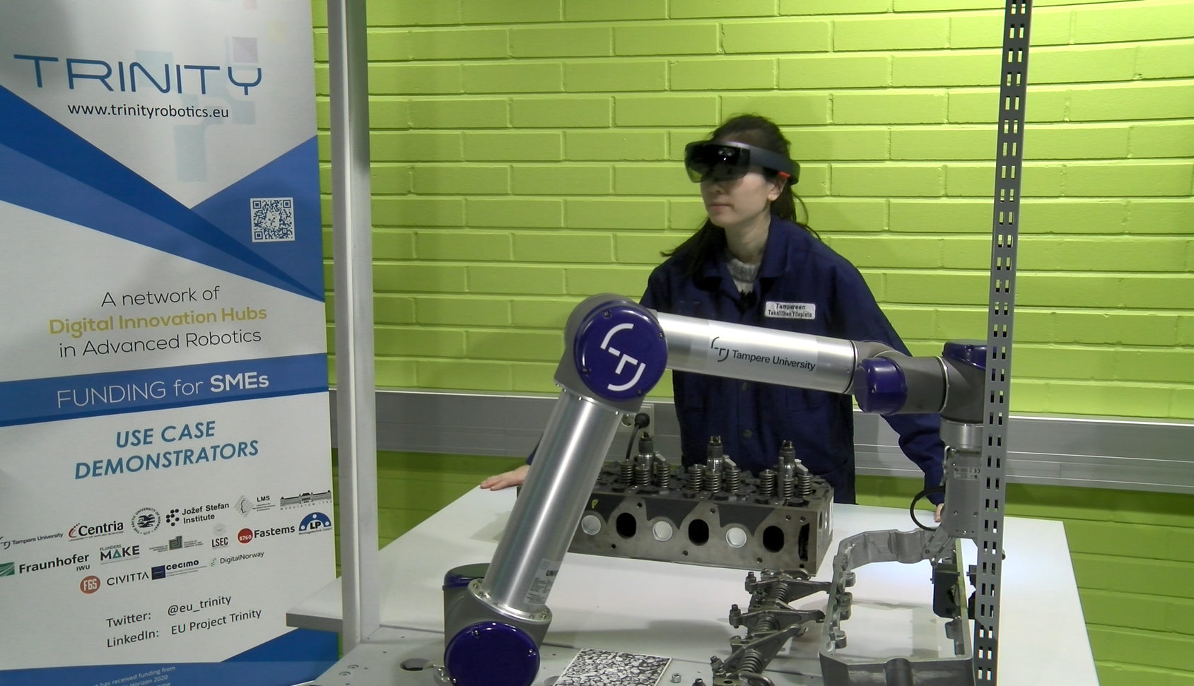
Generation of AR-based interface for human-robot collaboration: Increase the human operator awareness, safety and capabilities during a human-collaboration task in a shared workspace. Software module creates and visualize a dynamic safety hull around the robot as 3D holograms which are visualized using a wearable display, in this case, Microsoft HoloLens. Similarly, as in module 1, additional user-defined interface components can be created and projected to the workspace as 3D holograms.
Technical specifications
The overall description of the hardware requirements and the different software nodes in the module are shown in Fig. 9. The state-of-the-art head-mounted AR display is used to visualize the user interface components. The headset can operate without any external cables and the 3D reconstruction of the environment, as well as accurate 6-DoF localization of the head pose, is provided by the system utilizing an internal IMU sensor, four spatial-mapping cameras, and a depth camera. HoloLens is communicating with the Linux-based server using wireless TCP/IP. The Linux server synchronizes data from the robot to HoloLens and back. The usage of the interface components is monitored by the Kinect v2 sensor installed at the ceiling. A modified version of ur_modern_driver and univeral_robot ROS packages are used to establish a communication channel between the robot low-level controller and the projector node. Software running on HoloLens is responsible for creating and updating the 3D holograms projected on the workspace.
HoloLens, robot and depth sensor are all connected to a single laptop computer that runs the ROS Melodic distribution on Ubuntu 18.04 and performs all computing. Right now, only Kinect v2 and Universal Robot 5 are supported.
Inputs and outputs
The data is transferred via a standard ROS transport system with publish/subscribe semantics between robot, sensor and the server PC.
The TCP/IP Server node subscribes to topics /joint_states and /trinity/system_data where the robot joint values and the task-related data are published respectively. The joint values are used to calculate the shape and position of the safety hull. The text in the virtual information bars and the appearance of other interface components are based on the system data.

Figure 8 Description of the data transport layer
In addition, the TCP/IP Server node subscribes to /trinity/sensor/points topic where the depth measurements from the sensor are published. The measurements are used to calculate the usage of the interface components (e.g. is a human hand on the virtual stop button)
 Figure 9 Description of the data transport layer
Finally, the two-way communication between PC and HoloLens is done using the TCP/IP Server node. The node communicates with HoloLens using custom TCP packages with a fixed length.
Interface specification:
The main interface components are the same as in module 1 but everything is rendered in 3D. Interactive buttons (GO, STOP, CONFIRM OBJECT, CONFIRM) are modelled as spheres and information bar as a 3D plane. The safety fence is rendered as a polygonal mesh having semi-transparent red texture.

Figure 10 Wearable AR user interface
Formats and standards
ROS communication layer, ROS-industrial, OpenCV, Microsoft Visual Studio, Unity, Vuforia
Owner (organization)
Tampere University, Finland
https://research.tuni.fi/productionsystems/
Trainings
To learn more about the solution, click on the link below to access the training on the Moodle platform
Wearable AR-based interaction interface for HRC